DIY Safe Autodialer: The best DIY safe opening device on the internet
So, you love a good engineering puzzle. You see a challenge and your first thought is, „I could build a machine for that.“ If that’s you, let’s talk about the ultimate project: building a DIY safe autodialer.
While professional safe autodialer for sale models exist, their high cost is a major hurdle. For the DIY enthusiast, however, it’s about more than just the price; it’s the ultimate hobby. The real satisfaction comes from tackling the engineering challenge and the pride of building your own safe opening device from the ground up.
The genius in these projects is how they use smarts to outwit the lock, exploiting tiny mechanical flaws to slash the cracking time from days to mere minutes.
In this deep-dive, we will analyze and compare four standout DIY safe autodialer projects found on the internet. We’ll break down their different approaches, comparing everything from their core philosophy to their choice of motors, microcontrollers, and success-detection methods.
Whether you’re curious about the engineering or planning your own build, this guide will give you a complete map of the landscape. Let’s get started.
Learn from the Best: 4 Top DIY Safe Autodialer Projects
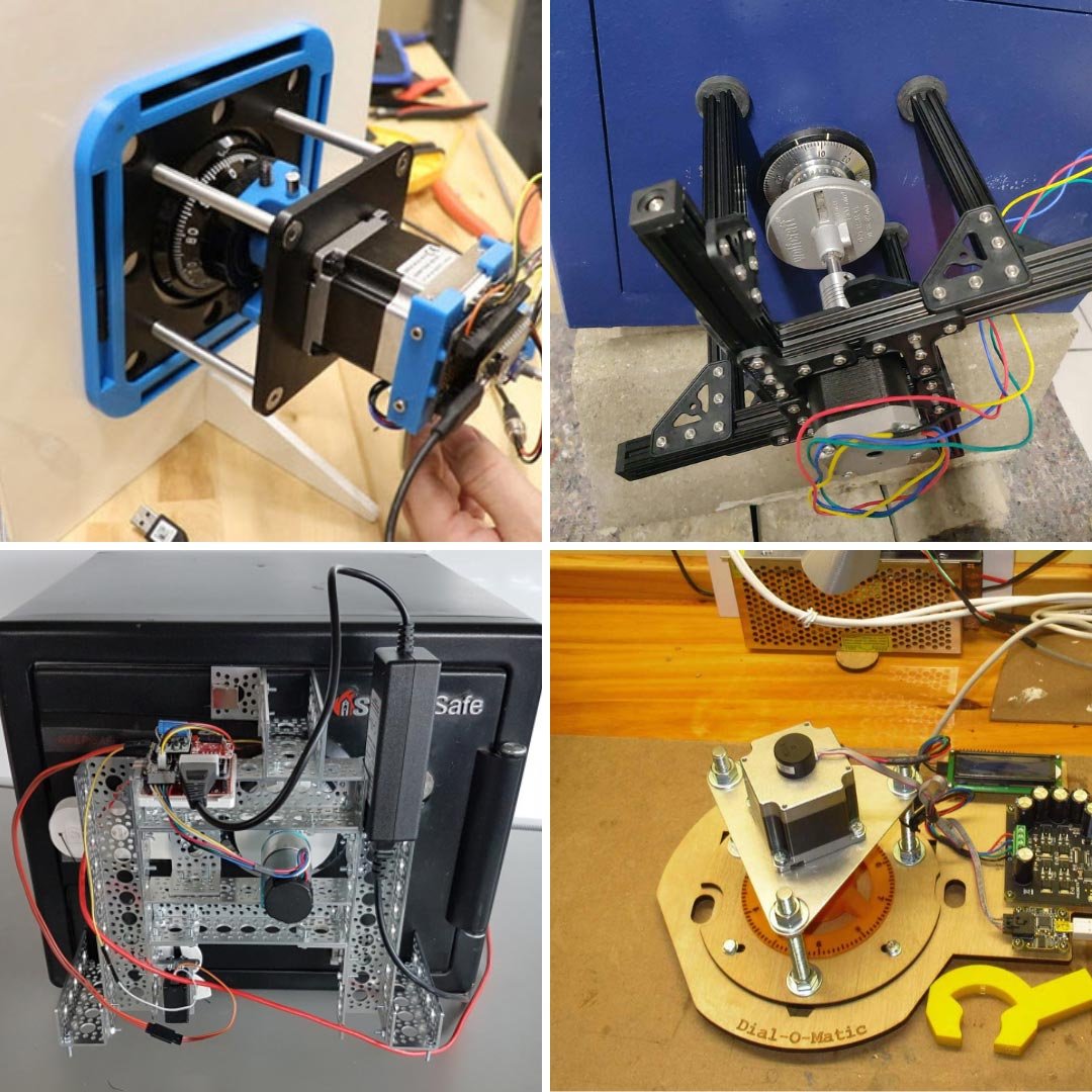
Now that we understand the ‚why‘, let’s get into the ‚how‘. We’ve scoured the internet and selected four fascinating DIY safe autodialer projects that perfectly illustrate the different paths you can take. Each has a unique philosophy and a different approach to solving the same puzzle. Let’s meet the contenders.
Show Component List
- Motor: Trinamic PD57-2-1076 NEMA 23 stepper motor with integrated driver
- Microcontroller: Adafruit ESP32-S2 TFT Feather
- Power Supply: 24V DC power supply
- Display: Integrated into the ESP32 board
- User Input: Rotary encoder
- Handle Actuator: High-torque hobby servo with metal gears, limit switch
- Frame: Laser-cut aluminum plates, aluminum tubes, screws
- Coupler: 3D-printed adjustable chuck (PLA and TPU)
Show Component List
- Motor: 12V DC gear motor
- Encoder: High-resolution optical encoder (8400 CPR)
- Microcontroller: SparkFun RedBoard
- Shield: Custom „Safe Cracker Shield“
- Sensors: Photogate for homing
- Handle Actuator: Standard servo with feedback
- Frame: Actobotics components, magnets
- Coupler: 3D-printed coupler with clamping hub
Show Component List
- Motor: Phidget 57STH56-2804B stepper motor
- Motor Controller: Phidget 1067_0B Stepper Bipolar HC Controller
- Encoder: Phidget HKT22 Optical Encoder with 1057_3B Interface
- Microcontroller: Raspberry Pi
- Frame: Laser-cut plywood, 3D-printed parts
Anatomy of a DIY Autodialer: A Head-to-Head Comparison
Every great project is a series of smart decisions. Now that you’ve met the four contenders, let’s put them on the workbench and see what makes them tick. We’ll break down their designs into the core systems—the brains, the muscle, and the senses—to understand why their creators made the choices they did.
1. The Brains: Choosing a Microcontroller
Every robot needs a brain, and the choice of microcontroller defines the project’s capabilities and complexity.
- The SparkFun build uses an Arduino-compatible RedBoard. This is the classic choice for the DIY community: simple, incredibly well-documented, and easy to get started with.
- The Digi-Key and eNBeWe projects both chose ESP32/ESP8266 boards. These are more powerful than a basic Arduino and come with built-in Wi-Fi, opening the door for features like sending you an email notification with the correct combination once the safe is open.
- The Tim Deaves build levels up to a Raspberry Pi. This isn’t just a microcontroller; it’s a full-fledged mini-computer. This allows for programming in a high-level language like Python and handling more complex software logic, which, as we’ll see, is key to its elegant design.
What this means: The choice ranges from the simple and reliable (Arduino) to the powerful and connected (ESP32) to the fully programmable (Raspberry Pi). There is no wrong answer; it just depends on the features you want.
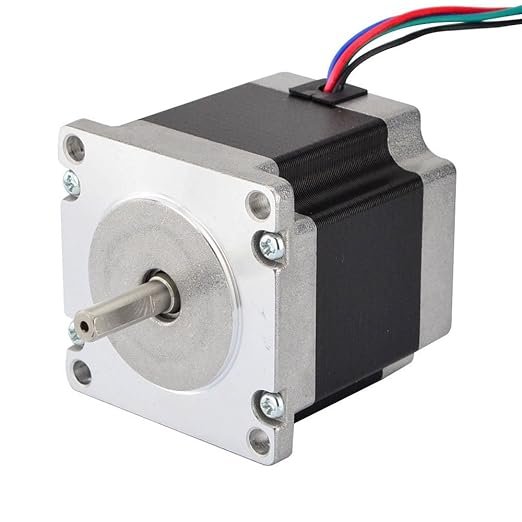
2. The Muscle: Safe Cracker Drive Systems (Stepper vs. DC Motor)
This is one of the most fundamental design choices: how do you spin the dial with precision?
- The Stepper Motor Camp (Digi-Key, eNBeWe, Tim Deaves): Three of the projects use stepper motors. Steppers are fantastic because they move in precise, repeatable steps without needing a sensor to tell them where they are (this is called „open-loop“ control). The Digi-Key project uses a high-end Trinamic „smart“ stepper, which is like a standard stepper with its own built-in brain for advanced features.
- The DC Motor Camp (SparkFun): SparkFun went a different route, using a standard DC motor combined with a high-resolution encoder. A DC motor just spins continuously, so the encoder is essential to give the microcontroller precise feedback on the dial’s exact position („closed-loop“ control). This choice was perfect for their algorithm, which needed to detect the subtle edges of notches in the lock.
What this means: Steppers offer simplicity and precision out-of-the-box. A DC motor with an encoder gives you smooth power and undeniable positional accuracy, but requires more complex control.
3. The Senses: How The DIY Autodialer Knows It Won
This is where the real creativity shines. How does the machine know when to stop?
Method 1: Feeling the Stall (Digi-Key & Tim Deaves): On many high-quality safes, the dial stops dead when the correct combination is entered.
- The Digi-Key machine uses its smart motor’s „StallGuard“ feature to electronically feel this hard stop. No extra sensors are needed.
- The Tim Deaves build has an incredibly clever, software-only solution. It constantly compares where the motor should be with where the encoder says it is. If there’s a mismatch, it means the motor has been physically blocked—success!
Method 2: Pulling the Handle (SparkFun & Digi-Key): Many cheaper safes require you to physically turn the handle to test a combination.
- The SparkFun robot uses a servo motor to pull the handle after testing certain combinations. It cleverly reads the servo’s own internal feedback wire to know if the handle moved all the way down.
- The Digi-Key machine also incorporates a powerful servo to turn the handle, making it a versatile hybrid capable of tackling both types of locks.
Method 3: The Human Eye (eNBeWe): The eNBeWe project uses the simplest method of all: no electronic detection. It was built with a constant tension on the safe door. When the right combination was hit, the door simply swung open on its own for the patient builder to discover.
4. The Skeleton: DIY Autodialer Frame and Coupler Design
A safe cracking robot is only as good as its frame. A rigid, stable connection to the safe is non-negotiable for accuracy.
- The Digi-Key project is the most robust, with a frame professionally machined from anodized aluminum and a sophisticated, 3D-printed adjustable chuck to grip the dial.
- The SparkFun build uses a modular Actobotics frame, like a high-end construction kit, providing great flexibility and strength.
- At the other end of the spectrum, the eNBeWe build proves what’s possible with minimal resources, using leftover MakerBeam parts and a hole-saw superglued to a coupler. It’s not pretty, but it absolutely worked.
What this means: While a professional frame is ideal, these projects prove that as long as the connection is stable, you can achieve success even with improvised, low-cost materials.
DIY Autodialer: A Head-to-Head Comparison
| Attribute | Digi-Key / Byte Sized Engineering | SparkFun | eNBeWe | Tim Deaves / Hackaday.io |
|---|---|---|---|---|
| Lead Developer / Organization | Zach Hipps / Digi-Key | Nathan Seidle / SparkFun | eNBeWe | Tim Deaves |
| Core Philosophy | High-quality, adaptable, and iterative development | Open-source, replicable, exploit-specific | Minimalist, improvised, low-cost | COTS modules, high-level programming |
| Motor Type | Stepper motor with integrated driver (Trinamic PD57-2-1076) | DC gear motor | Standard stepper motor | Phidgets stepper motor (57STH56-2804B) |
| Microcontroller | ESP8266, later ESP32-S2 TFT Feather | SparkFun RedBoard (Arduino-compatible) | NodeMCU (ESP8266) | Raspberry Pi |
| Feedback Mechanism | UART from Trinamic driver (StallGuard), Encoder (later) | External high-resolution encoder (8400 CPR) | None (Open-Loop) | Phidgets optical encoder (HKT22) |
| Success Detection | 1. Motor Stall 2. Servo + limit switch on handle |
Servo feedback (analog value) on handle | Manual (door swings open) | Discrepancy between target and actual encoder position |
| Frame Construction | Laser-cut aluminum, anodized | Actobotics parts | MakerBeam, improvised | Laser-cut plywood, 3D-printed |
| Dial Coupler | Adjustable 3D-printed chuck with TPU fingers | 3D-printed coupler with clamping hub | Hole saw with superglue | 3D-printed parts |
| Handle Actuator | Yes, high-torque servo with separate frame | Yes, servo with string pull | No | No |
| Algorithm Type | Optimized brute-force (tolerance exploitation) | Exploit-based (Set Testing on Disc-C indents) | Optimized brute-force (tolerance exploitation) | Sequential brute-force |
| Open Source Resources | GitHub (empty), Blog Series, Videos | GitHub (Code, CAD, PCB), Tutorial | GitHub (Code), Blog Post | Hackaday.io Page |
So, Which Path Should You Take For Your DIY Safe Opening Device?
Alright, we’ve torn down four amazing projects, from a beastly professional build to a brilliant hack made of spare parts. As you’ve probably realized by now, there’s no single “best” way to build a DIY safe autodialer. The best approach is the one that’s right for you, your budget, and the specific metal box you’re trying to open.
So, let’s figure out which project’s philosophy you should follow.
- If your target is a specific, common, low-cost safe…
…then the SparkFun approach is your playbook. Its entire design is a clever exploit for a known weakness. It’s not a general-purpose tool; it’s a highly specialized key. If you know your target’s weakness, this is the fastest path to success.
- If you’re facing an unknown or high-quality safe…
…then you should be looking at the Digi-Key build. This machine is a versatile beast. Its ability to detect success by either feeling the motor stall or by physically turning the handle makes it adaptable. It’s built for the unknown, where brute strength and flexibility are more important than a single clever trick.
- If you’re on a tight budget and love a good challenge…
…then the eNBeWe project is your inspiration. This build is proof that you don’t need expensive parts or a machine shop. If you have a spare motor, some scrap metal, and a whole lot of patience, you can absolutely get the job done. It’s the essence of the hacker spirit.
- If you love clean code and easy integration…
…then the Tim Deaves approach using a Raspberry Pi and Phidgets is for you. This path is perfect for someone who is more comfortable with high-level programming in Python and wants to use reliable, off-the-shelf modules to get a sophisticated system running quickly.
A Quick Word on Your Most Important Choice
As you saw in the comparison, your biggest decision is the motor. A Stepper Motor is the straightforward choice, giving you precision right out of the box. A DC Motor with an Encoder is more complex but offers smooth power and undeniable proof of the dial’s position. And if you can spring for it, a Smart Motor like the one in the Digi-Key build gives you the best of both worlds.
The Next Level: Where This Hobby Gets Really Wild
Think these builds are cool? The rabbit hole goes deeper. The true pros and advanced hobbyists are experimenting with even more sensitive methods:
- Acoustic Analysis: Imagine using a modified stethoscope to listen for the faint internal clicks as the lock’s gates align. It’s the digital version of what you see in spy movies and requires some serious signal processing to filter out all the noise.
- Torque Sensing: This is about „feeling“ the lock in micro-detail. Instead of just waiting for a hard stall, the software would look for tiny changes in motor current, trying to feel the friction as the lock’s internal parts slide past each other.